The OSI Model Explained
Developed in the 1980s, the Open Systems Interconnection (OSI) model has become the reference tool for understanding data communications. The model is divided up into seven easy to understand layers that each performs a specific task. Each layer operates with the layer above and below for to enable end to end communication between systems, or for end to end communication between networks/networked systems
The seven-layer model is broken down into:
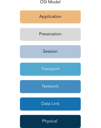
The seven layers can easily be remembered by using the acronym “All People Seem To Need Data Processing”. By separating the network into layers, network problems can be easily conquered and solved by viewing each section individually. This is especially apparent in the context of industrial networks, where 100% uptime is expected, and quick and easy troubleshooting is always welcomed.
Layer 1: Physical Layer
The Physical layer outlines the electrical and physical characteristics of a network. Ensuring transmission and recipient integrity of a network is fundamentally critical. If Side A is sending a 1, Side B, needs to receive a 1, based on a recognized standard of voltage and signal transmission lengths. The physical layer also describes cabling standards (Copper Ethernet, Fiber Optic, Twisted Pair, wireless, etc.) including pinouts and network interface cards (NICs). The layer is responsible for the transmission of unstructured raw data from a physical form which is then ready for further processing. When troubleshooting a network is the physical layer the first place to look. The most common issues with networks often stem from unhealthy connections such as damaged Fiber or broken Ethernet cables. If the physical connection is broken, all additional six layers will all be impacted
Layer 2: Data Link
The Data link layer provides node-to-node transfer for devices that are directly connected via a managed or an unmanaged switch by packaging and unpacking data in frames. The layer is usually broken down into two sublayers – Media Access Control (MAC) and Logical Link Control (LLC). MAC addresses are uniquely hardcoded addresses associated with physical and logical network interfaces. A switch can use this address to filter and forward traffic, providing entry-level security and congestion management. LLC is responsible for network encapsulation, enabling error and control checking via Cycle Redundancy Check (CRC). Ring and Mesh protocols commonly operate on a Layer 2 network, enabling resilience and redundancy for highspeed failover by utilizing MAC addresses and efficient switch processing.
Layer 3: Network Layer
The Network Layer provides a logical addressing system for packets to be routed to and from external networks. The Internet Protocol (IP) address enables multivendor intercommunication, which is fundamental for access and connectivity to the Internet Larger networks can further be divided up into bite-sized subnets enabling protocols such as Routing Information Protocol (RIP) and Open Shortest Path First (OSPF) to route traffic between networks based on predetermined values (Path Cost). Routing protocols can share information with neighboring routers enabling heterogenous communication within networks. When designed correctly, routing protocols can offer redundancy similarly to Layer 2 protocols. They can not however, reflect the same convergence due to additional processing. The main advantage of routed networks is a “next-hop” by design. An end-user can follow a packet through a network to determine for example why it may not communicate correctly or to increase efficiency.
Layer 4: Transport Layer
The transport layer provides end-to-end communication between devices on a network. It utilizes either the connection-orientated protocol, Transmission Control Protocol (TCP) or a connectionless protocol, User Datagram Protocol (UDP) for communication. Both TCP and UDP are widely used in a variety of applications and provide a method to access data from the session layer (Layer 5). TCP is used in Hypertext Transfer Protocol (HTTP) and the secure version (HTTPS) for example, as a method to communicate with a webserver. UDP is used in examples such as Network Time Protocol (NTP), which is responsible for keeping accurate system time/date. Industrial applications may use either TCP or UDP for various setups, with serial over IP being one of the most common. TCP operates as a server/client, enabling point to point communication, ensuring that if a packet is lost during transmission, it has the ability of being re-sent. In some cases that is not required, and traffic is unidirectional utilizing UDP. UDP enables communication between one central site, to multiple outstations either individually using unicast traffic or simultaneously using multicast traffic on a Layer 2 (switched) network.
Layer 5: Session Layer
The session layer provides a method for services between two end devices to sustain ongoing bi-directional communication across a network. Communication between applications on either end can exchange data for as long as the sessions last. The session layer establishes, manages, maintains, and terminates connections between applications, whilst also handling authorization and authentication functions. The layer also handles verification with data delivery.
Layer 6: Presentation Layer
The presentation layer provides data to be formatted for the 7th layer, the application layer. One way of looking at the presentation layer is to consider it as the translator for the network. For the application layer to understand the message, the presentation layer must translate data into a common format enabling an application to read and understand it. This layer is also responsible for compression during transmission which enables fast data rates. Video calls for example may be compressed and then recovered at the receiving end. This layer also offers the ability to encrypt a text message (a username and password for example). Outgoing messages are converted into a generic format at this layer, for them to be converted back to an understandable format of receipt.
Layer 7: Application Layer
The Application layer, considered the top layer of the OSI model, is most often where the user interacts with a device. Protocols such as HTTP, HTTPs, Secure Shell (SSH), Simple Network Management Protocol (SNMP) and File Transfer Protocol (FTP) operate at this level and are all very common in industrial networks. The top layer directly interacts with the software applications providing communication functions as required for the end-user.
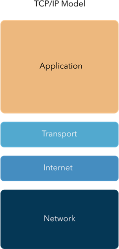
TCP/IP Model
The TCP/IP model is a concise version of the OSI model developed in the 1960s, with only four layers based on standard protocols. In some applications this is referenced, however, the seven-layer OSI model provides a more detailed breakdown and connection between each layer.
The four layers are:
The OSI model is a vital tool when learning about networks and should not be underestimated in its usefulness when developing a network or diagnosing faults. It is important to know the relationship between each layer to enable a holistic understanding of network fundamentals. If you want to learn more about the OSI model and how it relates to you and your industry, check out Westermo Academy where you can take courses on industrial networking.
Nuri Shakeer
International sales
For support inquiries, click here to contact Technical Support